Sale!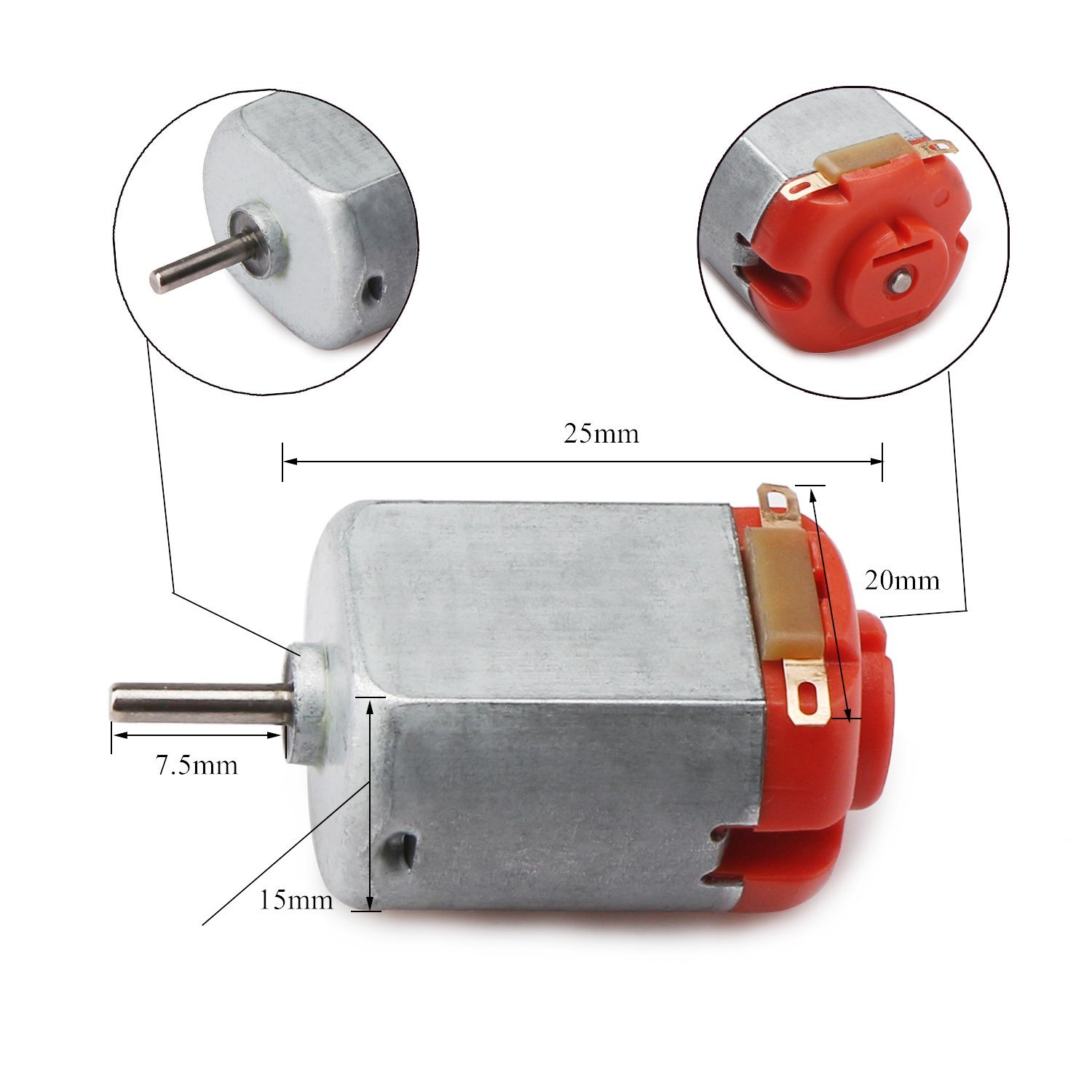
3-6V DC Motor Micro Motor Miniature Stepper Motor COM41 ,R14
$ 94.71
DescriptionThese are standard ‘130 size’ DC hobby motors. They come with a wider operating range than most toy motors: from 4.5 to 9VDC instead of 1.5 to 4.5V. This range makes them perfect for controlling with an Arduino where you are more likely to have 5 or 9V available than a high current 3V setting. They’ll fit in most electronics that already have 130-size motors installed and there’s two breadboard-friendly wires soldered on already for fast prototyping.Features:Operating Temperature: -10°C ~ 60°CRated Voltage: 6.0VDCRated Load: 10 g*cmNo-load Current: 70 mA maxNo-load Speed: 9100 ±1800 rpmLoaded Current: 250 mA maxLoaded Speed: 4500 ±1500 rpmStarting Torque: 20 g*cmStarting Voltage: 2.0Stall Current: 500mA maxWeight: 17.5 gramsGetting started 3-6V DC Motor Micro Motor Miniature Stepper MotorTo drive a DC motor you need a larger amount of current than Arduino board can give. For that reason you must use a transistor. Transistors have limits and maximum specs, just be sure those values are enough for your use. The transistor we are using for this tutorial is P2N2222A and is rated at 40V and 200mA, it just perfect for one toy dc motor. Note: If your motor needs more current than 200mA you can just buy another transistor (ask the staff in the electronics store). The connections below are the same. In this tutorial we will spin a dc motor from one direction, with different speed. You will be able to control motor speed from serial monitor!Step1: Hardware requiredFor this tutorial you will need:Arduino unoBreadboard220 Ohm resistorTransistor P2N2222ADiode 1N4148DC MotorStep2: Connecting the hardwareThe CircuitThe connections are easy, see the image above with the breadboard circuit schematic.Step3: Making the code and Upload it!/* Control Speed of a DC Motor from serial monitor More info: http://www.ardumotive.com/how-to-drive-a-dc-motor-with-transistor.html Dev: Vasilakis Michalis // Date: 13/7/2015 // www.ardumotive.com */ //Transistor 'Base' pin or input pin of motor driver ic to Arduino PWM Digital Pin 3 const int motorPin = 3; int Speed; //Variable to store Speed, by defaul 0 PWM int flag; void setup() { pinMode(motorPin, OUTPUT); //Set pin 3 as an OUTPUT Serial.begin(9600); //Init serial communication //Print a message: Serial.println("Give a number from 50 to 255."); //Why minimun value 50? Because with values below 50 the motor doesn't spin ;) Serial.println(""); //Blank line } void loop() { //Check if incoming data is available: if (Serial.available() > 0) { // If it is, we'll use parseInt() to pull out only numbers: Speed = Serial.parseInt(); flag=0; } //Valid range is from 50 to 255 if (Speed>=50 && Speed<=255){ //Send PWM value with analogWrite to Arduino pin 3 and print a message to serial monitor analogWrite(motorPin, Speed); //Print message only once if (flag==0){ //Print PWM value Serial.print("Motor spinning with "); Serial.print(Speed); Serial.println(" PWM"); flag=1; } } delay(1000); } // Then Upload Open the serial monitor from tools menu of Arduino IDE and try to send a number from 50 to 255. The result: Download the code from here and open it with Arduino IDE.dcmotor_tutorial.zipDownload File
Related products
-
Super Asia 3 Taps Water Dispenser HC-52Select options
This product has multiple variants. The options may be chosen on the product page
-
Super Asia 9 KG Top Load Automatic Washing Machine SA-809 PGSelect options
This product has multiple variants. The options may be chosen on the product page
-
Super Asia 3 Taps Water Dispenser HC-54GSelect options
This product has multiple variants. The options may be chosen on the product page
-
Super Asia 3 Taps Water Dispenser HC-56Select options
This product has multiple variants. The options may be chosen on the product page