Sale!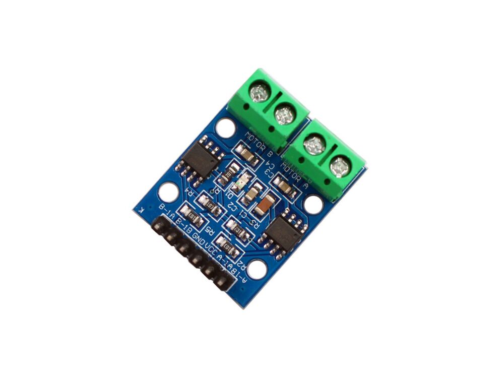
L9110 Dual-Channel H-Bridge Motor Driver Module – 12V 800mA COM31, R24
$ 91.73
DescriptionL9110, The ASIC device control and drive motor design two-channel push-pull power amplifier discrete circuits integrated into a monolithic IC, peripheral devices and reduce the cost, improve the reliability of the whole. This chip has two TTL / CMOS compatible with the level of the input. With good resistance, two output terminals can directly forward and reverse movement of the drive motor. It has a large current driving capability, each channel through 750 ~ 800mA of continuous current, peak current capability up to 1.5 ~2.0A. More than enough for a small DC motor.Specifications Input Voltage: 2.5V to 12V Output Channels: 2 DC Motors or 1 Stepper Motor or 4 Servos Full H-Bridges: 2Size: 31mm x 22mm x 12mmMax Output Current: 0.8 Amps per H-BridgePCB: app 2.8cm*2.1cmModule interface description: 6P black curved pin instructions: VCC Connected to external 2.5V-12V voltage GND Connected to external GND IA1 Connected to external microcontroller IO port IB1 Connected to external microcontroller IO port IA2 Connected to external microcontroller IO port IB2 Connected to external microcontroller IO port4P green terminal instructions: OA1 OB1 Connected to 2 pins of DC motor, no direction OA2 OB2 Connected to 2 pins of DC motor, no directionModule use instructions: Turn on VCC, GND, and the module power indicator is on; IA1 input high level, IA1 input low level, [OA1 OB1] motor forward rotation; IA1 input low level, IA1 input high level, [OA1 OB1] motor reversed; IA2 input high level, IA2 input low level, [OA2 OB2] motor forward rotation; IA2 input low level, IA2 input high level, [OA2 OB2] motor reverse Getting started with the L9110 Dual-Channel H-Bridge Motor Driver Module – 12V 800mAHG7881 (Another version of the L9110 motor driver) Dual Channel Motor Driver Module is a compact board that can be used to drive a small robots. This tiny module has two independent HG7881 motor driver chips which can each drive up 800mA of continuous current. 2.5V to 12V able to enabling this module to be used with both 3.3V and 5V microcontrollers. A PWM Pulse Width Modulation signal is used to control the speed of a motor and a digital output is used to change its direction. This module can also be used to drive a single 5-wire 2-phase stepper motor.Hardware requiredArduino UnoDC motorL9110 Dual-Channel H-Bridge Motor Driver Module – 12V 800mAConnecting the HardwareImportantly, we are currently feeding our motor 5v through our driver. This driver as explained above may work up to 12v (but never more than 1 amp) , or burn it. In order to achieve that we will reach 12v supply this voltage via an external source (This will do it in future tutorials), but basically would power the driver with the external source instead of the Arduino.Upload the sketchint M1_Left = 12; //Direccion int M1_Right = 11; //Direccion void setup() { pinMode(M1_Left, OUTPUT); pinMode(M1_Right , OUTPUT); } void loop(){ turn (1); delay(1000); //1 sg stop(); delay(250); //250ms turn(2); delay(1000); //1 sg stop(); delay(250); //250ms } void turn(int direction) { boolean inPin1 = LOW; boolean inPin2 = HIGH; if(direction== 1){ inPin1 = HIGH; inPin2 = LOW; } digitalWrite(M1_Left, inPin1); digitalWrite(M1_Right , inPin2); } void stop(){ digitalWrite(M1_Left, LOW); digitalWrite(M1_Right , LOW); }
Related products
-
Garnet Micro Bead EarringsSelect options
This product has multiple variants. The options may be chosen on the product page
-
Garnet Faceted Bead BraceletSelect options
This product has multiple variants. The options may be chosen on the product page
-
Garnet Faceted Bead EarringsSelect options
This product has multiple variants. The options may be chosen on the product page
-
Garnet Micro Bead Stretchy BraceletSelect options
This product has multiple variants. The options may be chosen on the product page