Sale!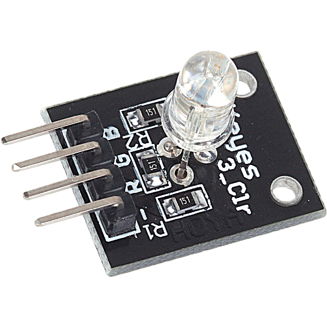
RGB Module KY 016 COM44, R18
$ 92.47
DescriptionRGB LED module LED is made of a plug-in full-color, by R, G, B three-pin PWM input voltage can be adjusted in three primary colors (red / blue / green) strength in order to achieve full color mixing effect. Control module with cool lighting effects can be achieved.Features:1. The use of plug-in full-color LED 2. With a variety of single chip microcomputer interface 3. The RGB tricolor current-limiting resistance to prevent burn out 4. is obtained by PWM adjusting three primary colors can mix different colors 5. Working voltage: 5 vModule Parameters:1. The PCB size: 15 mm * 10.6 mm 2. PCB color: black 3. USES 5050 full-color super bright LED 4. To prevent burn resistor LED 5. Can meet all kinds of single chip microcomputer 6. High light LED 7. Working voltage: 3.3 V / 5 V 8. Weight: 4 g 9. Can be used directly plugged into the motherboard Arduino, without dupont lines to connectGetting started with the RGB module KY 016Learn using RGB 3 Color LED Module KY-016 in Arduino. RGB LED module is capable of producing lights of different colors using a single LED. We can generate light of any color code through this module. In this, we will generate lights of all colors. We are using Arduino Uno and RGB 3 Color LED Module KY-016 for this. So, let’s start.Hardware requiredRGB module KY 016Arduino UnoJumper wiresConnecting the HardwareMake the circuit as per the given diagram. Connect red LED pin to pin 7 of Arduino. Then, connect the green LED pin to pin 9 of Arduino. Now, connect the blue LED pin to 8 of Arduino. Connect (-) pin of the module to the GND pin of Arduino. The RGB LED module will not require any limiting resistors.KY-016ArduinoRPin 11BPin 10GPin 9–GNDUpload the sample sketchThis is code for the RGB LED module in Arduino. Firstly, we declare pins for red, green and blue pins. Then, set the declared pins in output mode. We use the ‘for’ loop to generate light of all the color codes. The first loop generates color in decreasing order, whereas the second loop generates color in increasing order. You can use the serial monitor to determine the light of which color code is generated.int red = 7; // select the pin for the red LED int blue = 8; // select the pin for the blue LED int green = 9 ;// select the pin for the green LED int val;void setup () { pinMode (red, OUTPUT); pinMode (blue, OUTPUT); pinMode (green, OUTPUT); Serial.begin (9600); }void loop () { for (val = 255; val> 0; val –) { analogWrite (7, val); analogWrite (8, 255-val); analogWrite (9, 128-val); delay (10); Serial.println (val, DEC); } for (val = 0; val <255; val ) { analogWrite (7, val); analogWrite (8, 255-val); analogWrite (9, 128-val); delay (10); Serial.println (val, DEC); } }ResultsUpload the above-given code to the Arduino Uno Board after the components are set as per the Circuit Diagram. Now you can see RGB lights of different colors generating subsequently.
Related products
-
White PLA Board Cup 24ozSelect options
This product has multiple variants. The options may be chosen on the product page
-
White PLA Board Cup 16ozSelect options
This product has multiple variants. The options may be chosen on the product page
-
White PLA Paper Lid To Suit 12/16/24ozSelect options
This product has multiple variants. The options may be chosen on the product page
-
PP Plastic Flat Lid To Suit 8oz CupSelect options
This product has multiple variants. The options may be chosen on the product page